A recent thread on an appliance forum showed a James dishwasher that rolled into a space in the front of a wide range.
This page contains sketches of that mostly mechanical dishwasher made by James (Industries?) in the early 1950s. My parents bought theirs about the time I was born (1951); my dad repaired it many times during its lifetime, till it finally went beyond repair in the late 70s. By that time, I was a teenager; I was doing many of the repairs with him.
I never took pictures of the unit, so I sketched it from memory. I could probably build one...
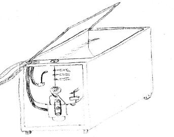
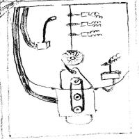
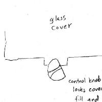
The dishwasher rolled on casters; it had a glass top. Everything inside, including the tub, was stainless steel (though some internal parts were brass). In the foreground you can see all the internal workings (see Fig 1), which will be detailed below. The knob at the top was the only control; it locked the cover while the unit was running, as shown in Fig 2.
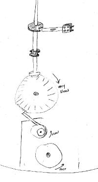
The entire timer (Fig 4) was mechanical. The vertical shaft rotated slowly, and three switches followed cams on the shaft. One switch turned on the entire machine; the motor ran continuously during operation. A second switch energized the water-fill valve, and a third started the pump.
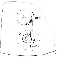
The motor, slung at the bottom, drove a v-belt that drove a high-speed impeller inside a housing within the wash compartment. The impeller flung water upward to be deflected around the tub.
The pump, whose pulley is in the center of the v-belt loop, sat idle until a solenoid yanked the pump assembly to one side. When that happened, the pump pulley followed the belt and the pump spun, emptying the tub.
The box at the right side of the tub is a float box: as the tub filled, the float would rise. A mercury switch (shown with some curly wires) then interrupted the power to the fill valve. A few moments later, the timer shut off power to the valve and mercury switch circuit.
At the left is the fill valve, which sprayed water from near the top of the tub. The spray would spread to cover most of the area of the tub, probably to better wet everything quickly.
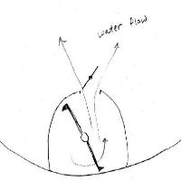
The impeller (Fig 5) ran the full length of the tub at the bottom; it was housed in a cylindrical metal housing for safety (it ran at full motor speed, about 1725rpm!). As it flung water out a slot in the top of the housing, the water struct another, slow-moving metal bar above the slot. This bar deflected water all around the tub. The deflector bar had a spiral twist to better deflect water effectively.
How did they slow things down?
The gearing required to slow down the rotational speed of the deflector would have been bulky and perhaps expensive. With the impeller turning at 1725rpm, the deflector at about 60rpm, and the timer shaft at 1/10rpm, how did they do this?
They used an eccentric cam drive (Fig 6). The high-speed shaft went through another metal shaft off-center. When the high-speed shaft turned, the off-center, or eccentric shaft, wobbled back and forth during operation. They attached a metal bar to the eccentric (this was done by a sleeve, but I've left out that detail in the drawings).
Now we have a little linear motion by the metal bar, similar to the way the push rods work on a steam locomotive. Those push rods convert linear piston motion to rotary motion at the loco's wheels. This application does the opposite. (If you could turn a loco's wheels, the rods would move the piston.)
The metal pushrod bumped the big gear, turning it one tooth for every back-and-forth motion of the pushrod. Thus the gear (and anything attached to it) turned much more slowly than the fast shaft driving the eccentric.
The first eccentric reduced the 1725rpm impeller speed to about 60rpm for the deflector shaft. The second eccentric reduced the deflector shaft' 60rpm to about 1/10rpm to drive the timer shaft. The timer shaft made a single turn to run the entire cycle in about 10 minutes.
I've only shown one of the blade switches and two cams. The switches were completely open-frame: you could easily get zapped if you touched the contacts while working on the unit. Timing adjustments could only be made by reworking the fiber cams to alter switch timing. If, for example, your water pressure was so low that the unit didn't fill by the time the switch cut off, you could cut the cam notch larger to extend the fill cycle. (The float always cut off the fill when the level was right, so having a longer switch time wouldn't hurt.) Since the rotation of the timer shaft, and thus the entire cycle, was fixed, you couldn't change that.
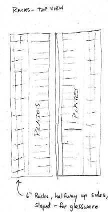
Loading was pretty simple (Fig 3). At the bottom of the tub there were parallel stainless wire racks, for plates and the like. Halfway up the tub sides (going the long way), there were 6" deep racks for glassware. These racks could fold upward for easier access to the bottom racks. Tableware (utensils) were put into a separate cage that you set somewhere inside.
I gazed into the glass top of this mechanical marvel as soon as I was tall enough to look in, until it became unfeasible to repair it – about 18 years.
|